
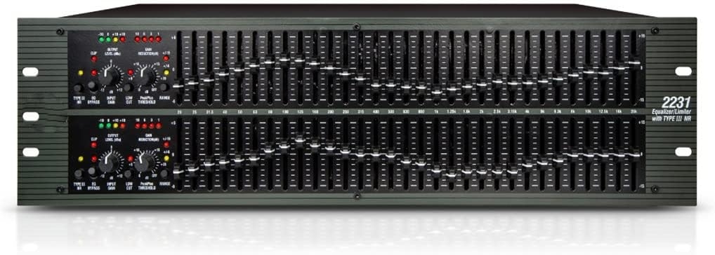

Description
Button Description
(1) Iupat Gain Control
This control sets the signal level to the equalizer. It is capable of-12dB to +12dB of gain. Its elfect is apparent by viewing the OUTPUTLEVEL BAR GRAPH.
(2) EQ Bypass
This switch removes the graphic equalizer section from the signal path.(See Block diagram on Page32.) The BYPASS switch does noL,however, alfect the INPUT GAIN,or LOW CUT filterss.
(3) Output Level Bar Graph
These four LEDs indicatc output level of the equalizer. The red LED is 3dB below clipping and is marked as +18dBu. It monitors the level at the output of the equalizer alter all other processing, includ-ing the limiter.
(4) Clip LED
This LED lights whenever any internal signal level rcaches 3dB below clipping which may occur whenany of the following bappen: 1) the imput signal is “hotter” han +22dBu,2) excessive gain is applied by the inputgain control. or 3) excessive boost is applied using the frequency sliders.
(5) Gain Reduction Meter
These four L.EDs indicate the amount of gain reduction being induced by the setting of thePeakPus TM LMITER THIRESHOLD control as the signal level from the graphic EQ section exceeds this limiterthreshold setting.
(6) PeakPlusTM Limiter Threshold Control
This control engages the PeakPlusTM limiter. It scts the threshold level at which 00:1 gain reduction will begin to occur. Its design is borrowed from the patent pending PeakStopPlusTu Limiter found on the popular dbx 1066 and 1046 compressor/limiters. I1 is capable of a range of OdBu through “OFF” (+24dBu). When the threshold control is set to“OFF”, the limiter is effectively disabled, and no gain reduction will occur
(7) Type IIT TMNoise Reduction Switch
The switch engages the dbx Type IT Noise Reduction circuit withinthe EQ.
(8) EQUALIZER SECTION
These calibrated, detented controls adjust the amount of cut o


Reviews
There are no reviews yet.